- 40 years of Canadian Innovation
Bridge Structural Analysis, Design and Evaluation Software
Streamline your engineering projects and Optimize workflow efficiency with an integrated Structural Analysis, Design and Evaluation Software.

Streamline your engineering projects and Optimize workflow efficiency with an integrated Structural Analysis, Design and Evaluation Software.
3D Bridge Structural Analysis, Design and Evaluation, including Prestressed girder bridges (CSA S6)
Automated tool for design and evaluation of steel girder bridges with wood decks (CSA S6-19)

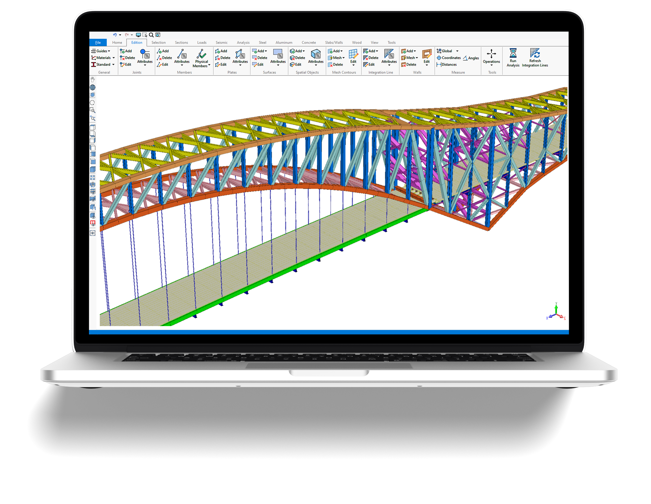
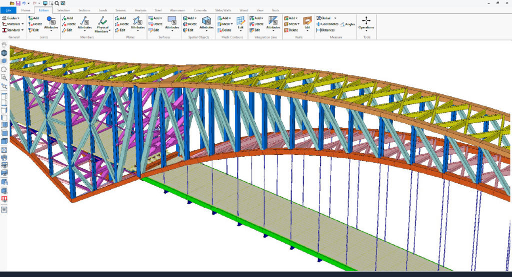
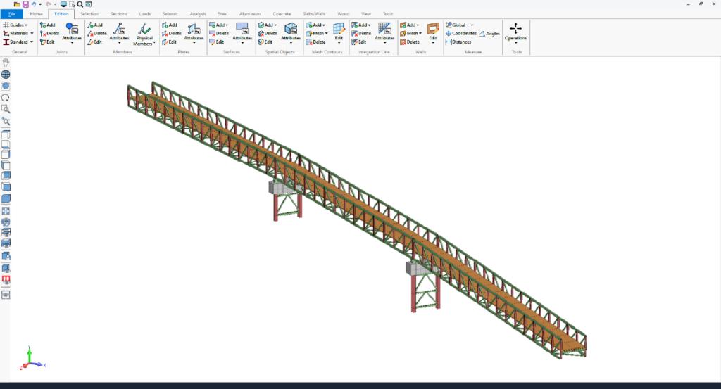
The BSE™ software is a fully integrated analysis, design and evaluation software for bridges. The software accounts for steel, reinforced concrete, composite, prestressed girder bridges and steel-wood bridges.
This 3D frame analysis software offers intuitive modeling features, comprehensive structural analysis capabilities and powerful design tools. The BSE™ software is user-friendly, easy-to-use and built on a ribbon-based interface, offering a streamlined design element where tools, commands, and options are conveniently organized into tabs and groups for effortless access and navigation.


Bridge structural software for professional engineers.
The BSE software features comprehensive state-of-the-art structural analysis methods, including:
• Finite Elements Analysis (FEA) including plates and shell elements
• P-Delta Analysis, Linear and Nonlinear Analysis, Buckling Analysis
• Static Equivalent Seismic Analysis, Seismic and Dynamic Time-History Analysis
• Non-linear analysis using load control and displacement control strategy
• Non-linear springs
• Torsion including restrained warping of open sections
• Linear and exact non-linear cable elements
• Direct Analysis Method (DAM) and the Effective Length Method (kL) for AISC 360
• Frequency and Response Spectrum Analysis
• Possibility to add non-structural components using Spatial Objects and Spatial Loads
• Advanced Section Stress Analysis and Built-up sections, and more analysis features
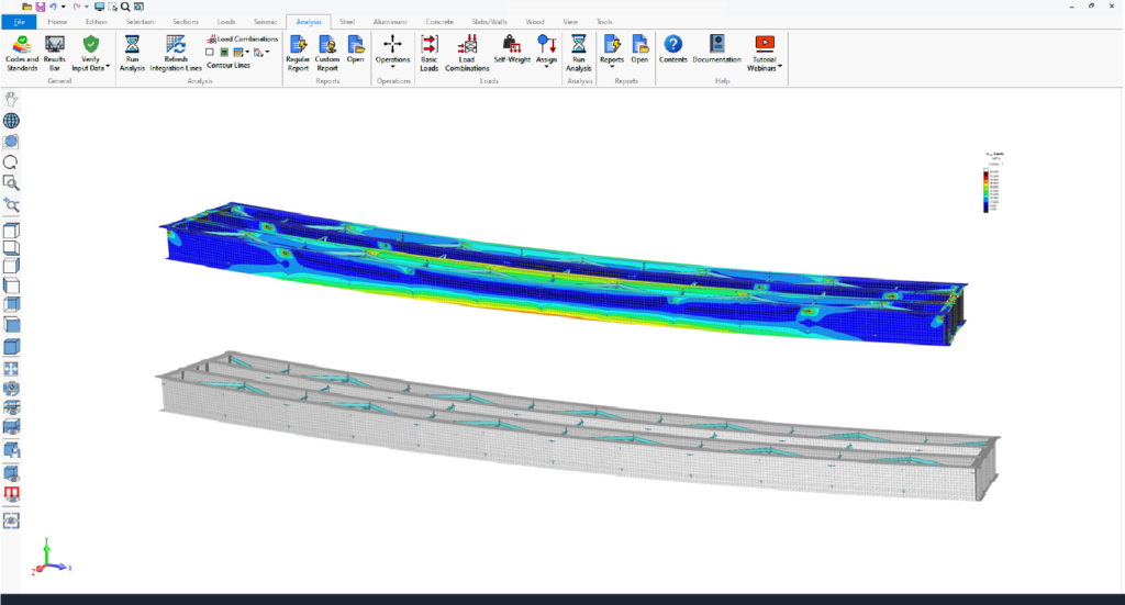
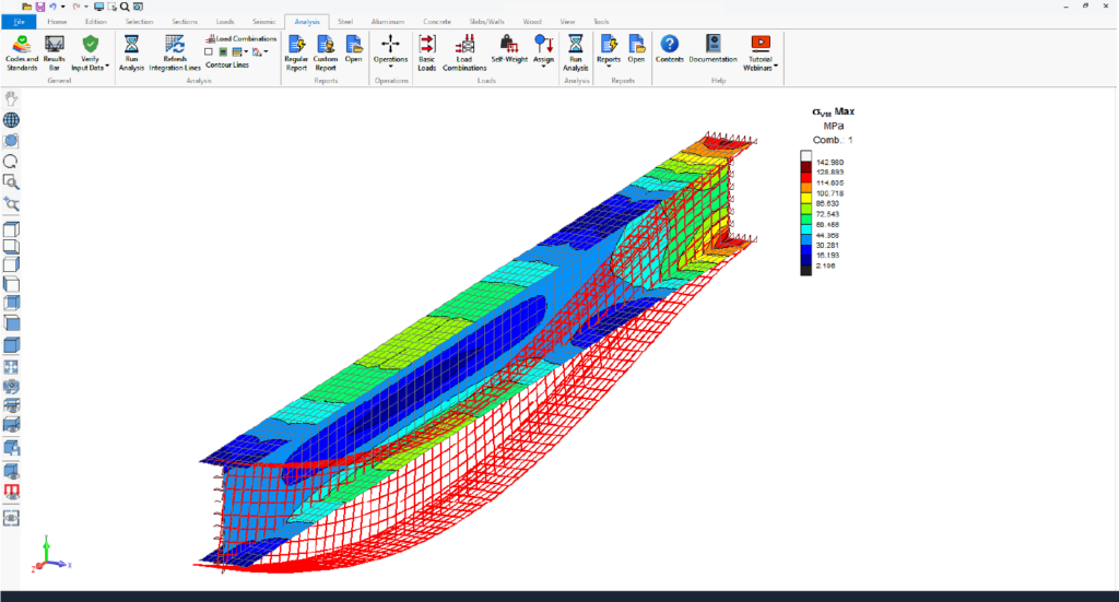
The BSE™ software allows users to animate analysis results, including static, P-Delta, buckling, seismic, and dynamic analyses. This visualization highlights displacements, internal forces, stresses, reactions, mode shapes, and time-history data, offering clear insights into structural behavior.
Animating envelopes focuses on critical regions, simplifying complex data for better decision-making during dynamic events.
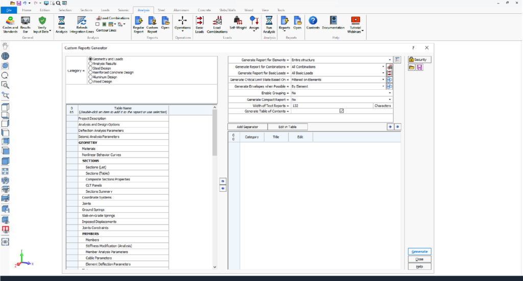
BSE™ software offers advanced custom reporting tools, enabling users to create tailored, professional reports with ease. With options to select relevant data, add individual or multiple tables, and customize settings, users can design layouts that meet specific project needs.
Editable titles, table reordering, and predefined templates enhance efficiency, while saved custom layouts streamline future reporting. Reports can be customized and exported to Microsoft Word and Excel, streamlining workflows.
BSE™ software features an intuitive, ribbon-based graphical user interface powered by DirectX 11 and OpenGL 2.0 for enhanced performance. Users can efficiently create, analyze, and design complex models, visualized as lines, wireframes, or 3D solids.
Users benefit from key functionalities such as automated mesh generation, detailed element creation, and transparency options for components like members, plates, surfaces, spatial objects and panels.
The software supports metric, imperial, and mixed unit systems, which can be modified at any time.
BSE™ software offers versatile modeling tools to create bridge structures efficiently. Key features include local coordinate systems, linear or circular construction lines, and automated commands like move, rotate, extrude, and subdivide.
Models can be edited graphically or via spreadsheets, with options for batch or individual element creation. Persistent groups, advanced selection tools, and renumbering options enhance productivity. Attributes can be set graphically or in spreadsheets, and surfaces facilitate load transfer and self-weight calculations.
Results and input data can be visualized, printed, and exported with flexible options for customization, reporting formats, and graphics sharing.
• Visualize results graphically or numerically.
• Print input data and results for the entire structure or specific parts using graphical selection or element ranges.
• Customize lists of input data and results for printing.
• Reports available in multiple formats: SAFI™ reports, Excel, Access, and ASCII text files.
• Graphics can be printed or copied to the clipboard for use in other programs.
A structural analysis software for professional engineers.
Canadian Highway Bridge Code - CSA S6
Perform multiple simultaneous or non-simultaneous standard and nonstandard moving loads analysis on simple and complex trajectories.
Comprehensive library of over 40 standard trucks and a moving load editor for user-defined trucks and trains.
Moving loads are transferred to selected elements of the model. Impact factors can be specified for an entire truck load, per axle, or for lane loads.
Axles can be raised as required by certain bridge design codes. Supports lateral distribution factors for moment, shear, and deflection.
Response envelopes generated for any combination of moving loads, lane loads, and non-moving loads.
Incremental analysis to account for staged construction.
Load factors can be determined automatically when evaluating an existing bridge.
Associated forces and maximum values can be obtained at any point of the structure using the advanced query engine.
BSE allows querying of analysis results and associated results at any point of the structure.
Design of concrete members subjected to various analyses, including linear, P-Delta, non-linear, seismic, dynamic, and moving load analysis.
The program accounts for second-order effects using simplified methods from design codes.
Considers effects of lateral drift and internal member deformations together or independently.
Longitudinal and transverse beam reinforcement determined automatically.
Pile reinforcement determined automatically.
All required reinforcement and development lengths calculation.
Allows editing of calculated reinforcement and additional resistance verification.
Offers a cyclic design method to align with practical user requirements without manual calculations.
Allows full editing of all reinforcement bars.
Enables multi-cycle design and verification.
Supports design of partial structures.
Design of longitudinal reinforcement, stirrups, and column reinforcement for common concrete section shapes.
Display of reinforcement layouts, resistance curves, and interaction diagrams graphically.
Consideration of longitudinal reinforcement and bent bars for bending resistance.
Consideration of straight or inclined stirrups and bent bars for shear and torsion resistance.
Consideration of column reinforcement for combined axial and bending loads
Supports design of continuous members.
Handles design for bending, shear, torsion, and combined axial and bending forces.
Perform steel verification, including section classification, resistance, and stability checks per applicable codes.
Calculate bending, compression, tension, shear, torsion, warping, and combined resistance of steel elements.
Account for long-term deflections.
Effective or full composite inertia in analysis.
Fully support transverse, bearing, and longitudinal stiffeners.
Support total and partial composite action with automatic determination of required studs.
Define custom studs as needed.
Use plain concrete slabs or concrete slabs cast on steel decks.
Choose from user-defined or standard steel decks.
Determine load factors automatically based on Chapter 14 of the CSA S6 code.
Compute resistance factors (U) automatically as per Chapter 14 of the CSA S6 code.
Accommodate standard traffic loads and special permit loads.
Define dead load classes for each basic load (D1, D2, and D3).
Assign moving load classes to each basic load, including Normal traffic, alternate normal traffic, PA, PB, PC, and PS.
Specify system behavior, inspection level, and reliability index for each bridge element.
Determine element behavior automatically for each component of the bridge.
Provide forces, resistances, limit states, and live load capacity factors for all elements in the model.
Retrieve any bridge analysis result at any point in the structure.
Generate reports for a specific point, a beam, or the entire bridge.
Access results for truck loads, lane loads, combined truck and lane loads, and any load combination.
Query static load results based on a defined set of criteria.
View results with truck position and direction for accurate assessment.
Display forces associated with queried results for better analysis and verification.
Perform section classification, resistance, and stability checks according to the applicable code.
Compute bending, torsion, warping, compression, tension, shear, and combined resistance for steel and composite elements.
Analyze results from linear, P-Delta, non-linear, seismic, dynamic, and moving load analyses.
Conduct a complete deflection verification based on a comprehensive set of criteria.
Analyze, design, and evaluate beams prestressed by pre-tension with minimal user input.
Automatically generate the model once geometric data and material properties are provided.
Reduce model creation time significantly through an automated pre-tension module.
Perform analysis and design of precast concrete bridge girders with pre-tension according to: AASHTO, NEBT, NBPS, CPCI, Custom precast shapes
Automatic & custom transverse strand layouts.
Support for straight strands with one or two raised points.
Standard and custom moving load envelopes for truck and/or lane loads.
Pre-tension losses calculated using specified design codes or a step-by-step method.
Design of precast girders for multi-span bridges with composite slab action.
Stirrup and steel reinforcement design at supports.
Consideration of thermal effects.
Secondary effects from creep and shrinkage included in calculations.
Time-dependent girder deflection analysis.
Evaluation in accordance with Chapter 14 of CSA S6.
Combines highway live load results with other loads (dead loads, additional dead loads, live loads) to generate global solutions and response envelopes.
Provides tools for prestressed bridge girder design.
Allows design using:
Standard AASHTO, CPCI, NEBT, NBPS sections and
Custom precast cross-sections
Supports both standard and custom highway moving loads.
Standard moving loads available: CL-625 (CSA S6), CL-625-ONT (CSA S6), CL-W (CSA S6), CF3E-500 & CF3E-W (Quebec), CFHN-1500 & CFHN-W (Quebec), QS660 (Quebec), MTQ-340 (Quebec), CS600 (CSA S6-88),OHBDC (Ontario), Egyptian Loads, AASHTO (USA)
Calculates lateral distribution coefficients based on CSA S6 requirements.
Available for both standard and custom precast sections.
Standard sections have built-in strand layouts (editable).
Custom sections require a user-defined transverse strand layout.
Maximum number of straight and inclined strands specified for standard sections.
Narrow top flange
Wide top flange
Bulb tee sections
BSE™ Software
3D Structural Analysis, Design and Evaluation Software
Our team is here to assist with any inquiries—whether you're exploring options, scheduling a demo, requesting pricing, or seeking help to get started with the BSE™ software.
Take the next step to discover BSE™ Software by completing the following form. One of our experts will get in touch with you shortly. We look forward to assisting you with your inquiries and providing you with the information you need.
Ready to get started? Contact us today to explore the BSE™ software.