Deflection calculations of reinforced concrete slabs
GSE™ Features
GSE™ Features
TECHNICAL FEATURE // Deflection Calculations of Reinforced Concrete Slabs
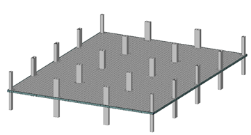
Concrete buildings are widely used in the construction industry. In such structures, slabs are key structural elements resisting the gravity and live loads of each floor. The design of concrete slabs is an iterative process. Mainly two aspects must be verified i) the resistance and ii) the deflections of the slabs. Even though the amount of reinforcements are chosen to resist the structural loads, a particular attention must be provided to the deflections of the slabs. Such deflections verification may indicate a need of additional reinforcements or a need to increase the thickness of the slabs.
Hence, the cracked deflections calculation of concrete slabs has been developed. The cracking phenomenon increases the overall deflections of the slab. The service limit states ensure that the slab deflections do not exceed the given limit values to avoid causing serviceability problems.
Regarding serviceability, a particular attention must be provided to ensure that non-structural elements are not damaged by the building deflections. The construction steps are analyzed in order to properly assess the total deflections of such non-structural elements after their installations. In GSE™ software, the construction steps are represented by load combinations for the dead weight, the sustained dead weight and the live loads. Other parameters, required by the various standards may be edited by the end user.
The deflections of concrete slabs are composed of: immediate deflections and time-dependent deflections. The immediate deflections are calculated for the selected load combinations. The shrinkage and creep phenomenon are time-dependent effects causing deflections over long periods of time. The overall deflections of the building is a combination of both the immediate and time-dependent deflections.
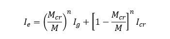
The immediate cracked deflection calculations require an iterative analysis procedure where the loads are applied progressively. The initial finite element stiffness is calculated using the concrete isotropic elastic properties. As the loading intensity increases, the flexural efforts in the slabs also increase. Thus, cracks may form near high flexural effort areas. At those locations, the slab sectional inertias change and the concept of effective inertia Ie is used. The effective inertia is calculated according to the uncracked inertia Ig and the fully cracked inertia Icr. A well-known equation to calculate the effective inertia Ie is presented below:
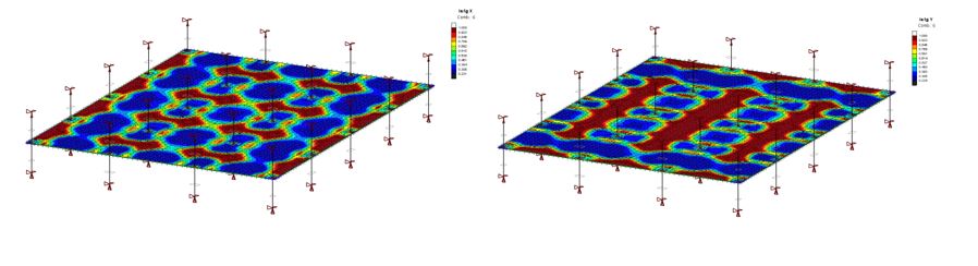
The shell finite elements effective inertias Ie in both principal reinforcement directions (Iex & Iey) are calculated and the shell elements stiffness are modified, thus requiring an orthotropic shell finite element formulation.
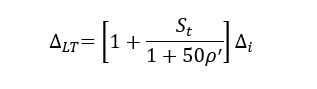
The time-dependent deflections are calculated using the cracked concrete immediate deflections of the specified load combinations. In GSE™, the load combinations management for the cracked concrete deflections has been automated. The CSA A23.3 proposes the following equation to calculate the long-term deflections. The ACI 318 equation is very similar.
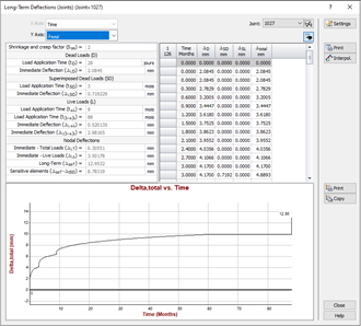
The time-dependent deflections are computed for each specified load combination. Also, the total deflection over time curve is calculated. Deflection results are provided for key load application times and are displayed graphically.
In order to calculate the service limit state, GSE™ automated the slab spans detection. For each load combination and span, the Serviceability Limit State (SLS) ratio is calculated using the long-term deflections and the span length and compared to the relative deflection limits (L/x) defined by the user. The user may easily verify if the serviceability limit states are respected or if more reinforcements are required in some portions of the slab.
GSE™ Software
3D multi-material analysis and design software for CLT, Mass Timber, Light-Frame Wood, Steel, Cold-Formed Steel, Reinforced Concrete, Automated Slab and Foundation design, and Aluminum.