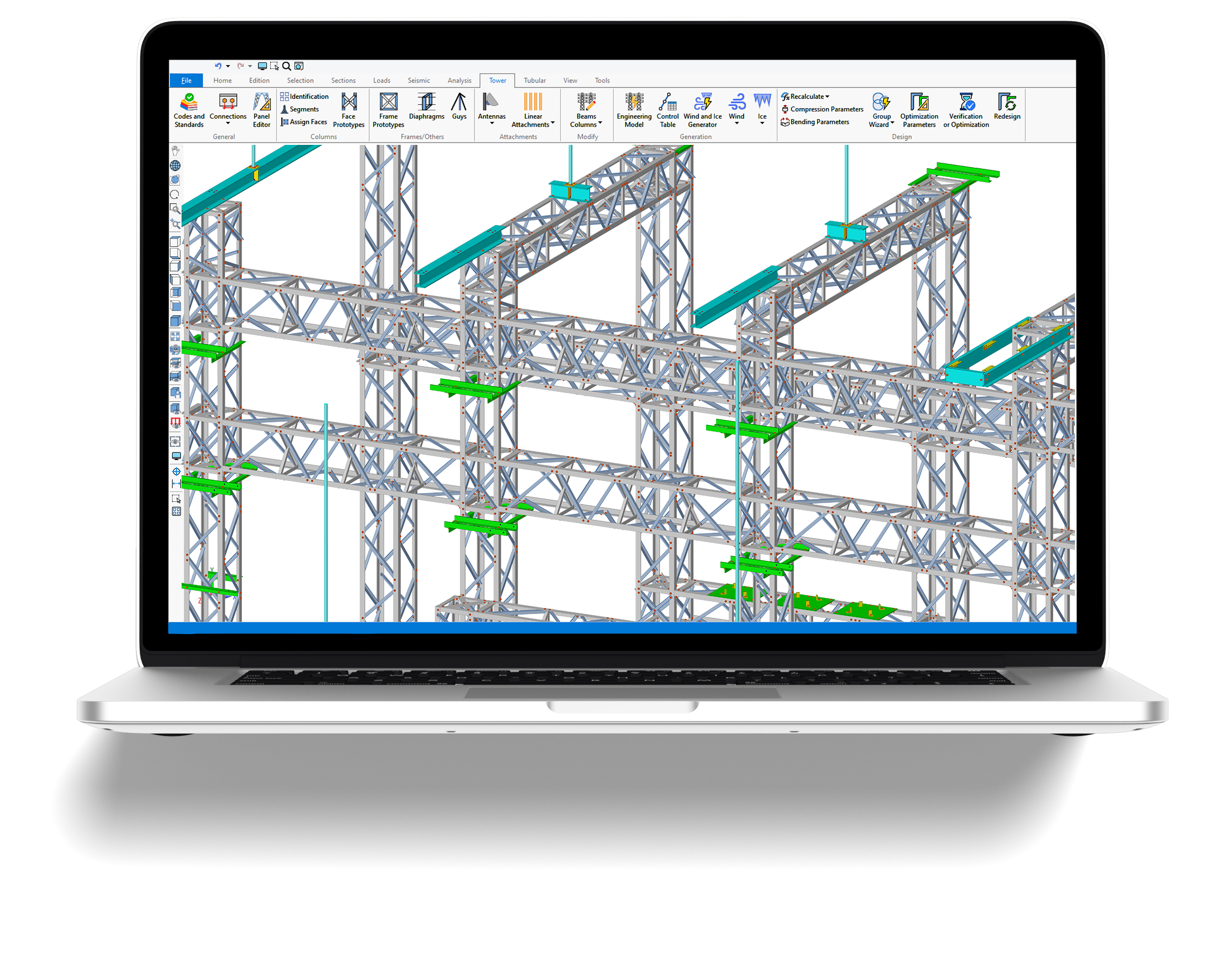
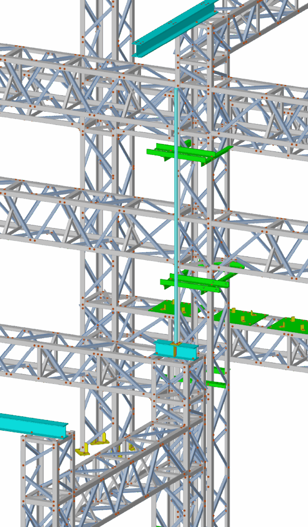
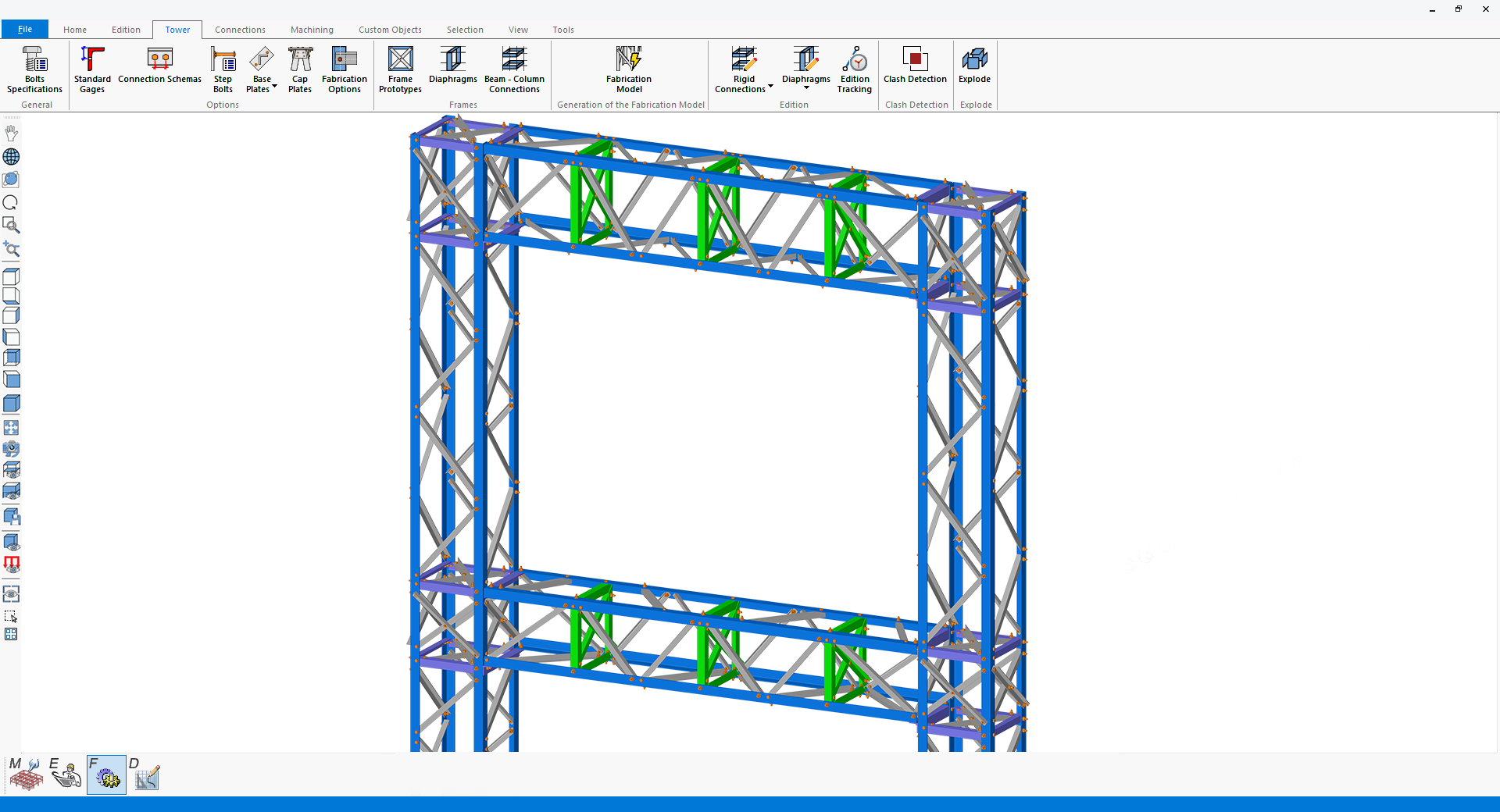
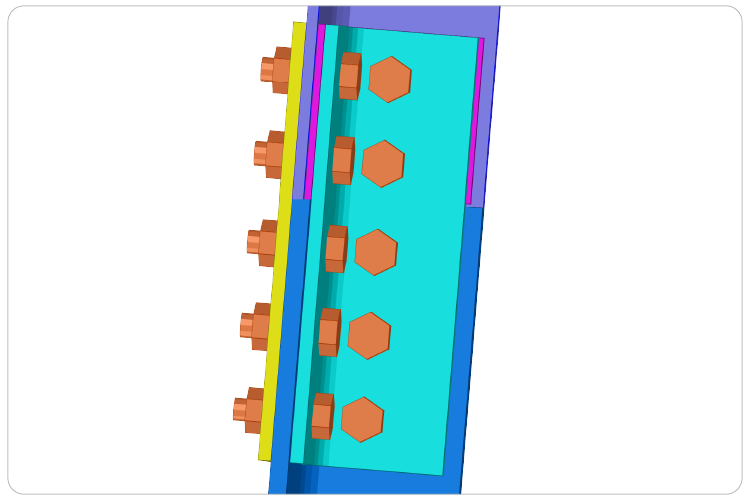
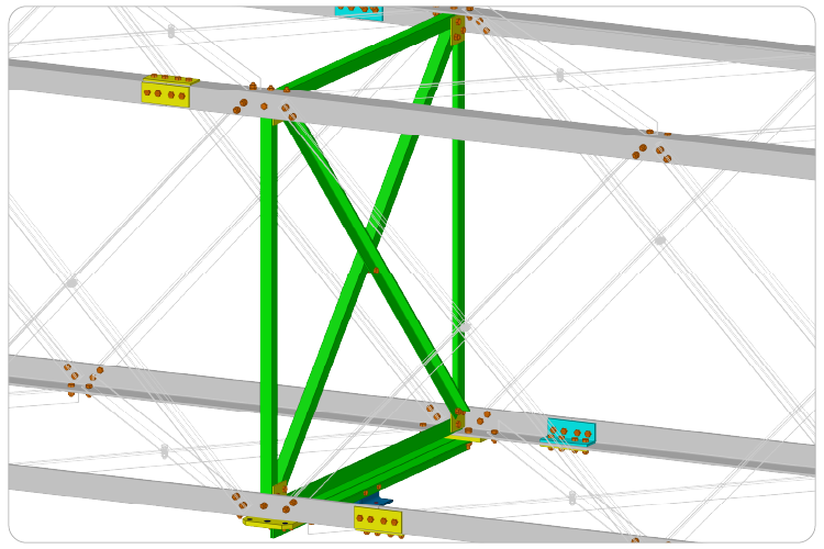
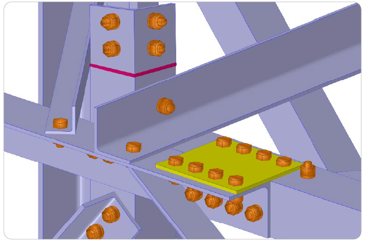
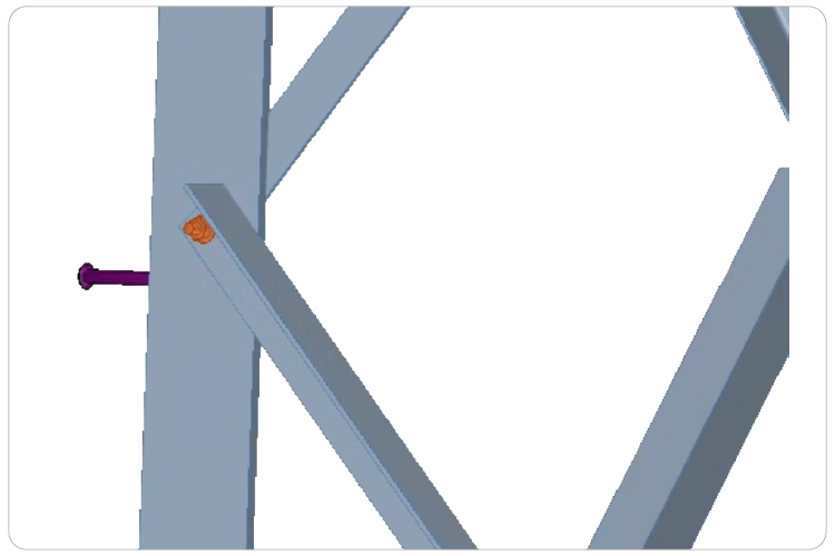
End-to-end integrated solution in a single software environment
Parametric modeling of substations and transmission towers with automated geometry, bracing, joints, and connection details.
Structural analysis and design of substations and transmission towers in compliance with applicable codes and standards.
Smart fabrication models with customizable connections, machining operations, and clash detection to ensure accurate, build-ready structures.
The detailing phase involves extracting manufacturing 3D and 2D drawings, engineering drawings, and detail drawings necessary for fabricating components, including those required for CNC (Computer Numerical Control) machine tools.
Dallas, Texas ǀ September 14-18, 2025
Parametric Tower Modeling
Users can model structures using an intuitive graphical user interface powered by DirectX 11 and OpenGL 2.0 for increased speed and capabilities and generate executive and customizable formatted reports in Microsoft Word and Excel worksheets.
The VTS® software is a technology built on a ribbon-based interface, offering a streamlined design element where tools, commands, and options are conveniently organized into tabs and groups for effortless access and navigation.
The ribbon-based graphical user interface of the VTS® software allows to create, analyze and design large and complex models quickly and easily. Models can be shown as lines, wire frames, or can be rendered as 3D solids. Functionalities of the VTS® program allow to generate automatically detail elements in an automatically generated mesh perimeter. An object transparency option is available for various components such as current selection, solid members, plates, surfaces, spatial objects, panels.
Flexible Tower & Substation Modeling
• Create lattice towers (self-supporting or guyed) with automatic generation of legs, bracing, and connections
• Model substation steelwork with individual columns/beams and automatic beam-column joints
• Primary-secondary configuration for columns and beams to simplify large substation modeling
• Add horizontal bracing at any elevation for columns and beams
• Connection schemes and bolt definition
Wizard-Driven Parametric Tools
• Rapid model generation for both towers and substations
• Built-in panel and bracing libraries
• Panel editor and user-defined panel libraries
• Anchor rod pattern generator for base-plate design
• Auto-generation of wind and ice loads on all structural and non-structural elements
• Full control over segment configuration, bracing patterns, leg sections and extensions, crossarms, and auxiliary framing
Robust Structural Analysis Suite
• Static linear analysis, Nonlinear analysis, P-Delta analysis, Buckling analysis, Frequency analysis, Seismic and Dynamic analysis, Nonlinear cable modeling, Tension-only members
Supported design codes
• ASCE 10-15 for latticed towers
• ASCE 48-19 for tubular sections
• AISC 360 / CSA S16
Applied Loads and Profiles
• Dead, wind, ice, and thermal loads
• User-defined wind loads
• Concentrated, uniform, trapezoidal loads on members and joints
• Spatial object loads
• Automatic calculation of wind pressure, drag coefficients, and gust and topography factors
Design Checks include
• Tension and Compression
• Connection checks: shear, bearing, block shear, tear-out
• Bending (single and combined)
• Torsion and Warping
• Slenderness and Buckling
• Anchor rods
• Base-plate design for tubular sections
• Tower tension-compression and deflection diagrams
• Design checks beyond angles including W, T, HSS and built-up sections
Structural Analysis & Design
Engineering of transmission lattice towers and electrical substations is performed seamlessly within VTS®, aligning with the ASCE standard. The software offers comprehensive structural analysis capabilities, including P-Delta, nonlinear, buckling, frequency, seismic, and dynamic analyses, with fully integrated design verification.
VTS® accelerates structure creation using an expansive library of panel types and parametric tools. Automatic generation of wind and ice loads is supported per the selected design code, while a rich repository of panel, rigid connection, and diaphragm prototypes streamlines the modeling process.
Results can be reviewed numerically or graphically, with color-coded charts that clearly visualize limit states across the entire structure or targeted members. All geometric and design parameters — including slenderness ratios and force coefficients — are computed automatically, but remain user-editable through intuitive graphical or tabular interfaces. Member grouping by shared properties further simplifies both modeling and interpretation.
Smart, customizable fabrication model
The fabrication phase involves performing fabrication operations on structural components such as cuts, notches, holes, bolting plates, connection design, and welding.
The Fabrication phase uses the structural model directly from Engineering Mode to generate a complete, production-ready fabrication model. VTS® automates detailing for direct bolt connections, splices, base plates, cap plates, gussets, step bolts, and more, minimizing manual work and ensuring accuracy.
Fabrication operations such as cuts, notches, holes, bolting plates, and welds are intelligently applied, with connection designs optimized for real-world manufacturing. Users retain full control to modify details via intuitive graphical or tabular tools.
The result is a fully detailed structure, ready for fabrication output, reducing errors, accelerating delivery, and maintaining full design integrity.
Connections
• Auto-generated connections with manual adjustment options
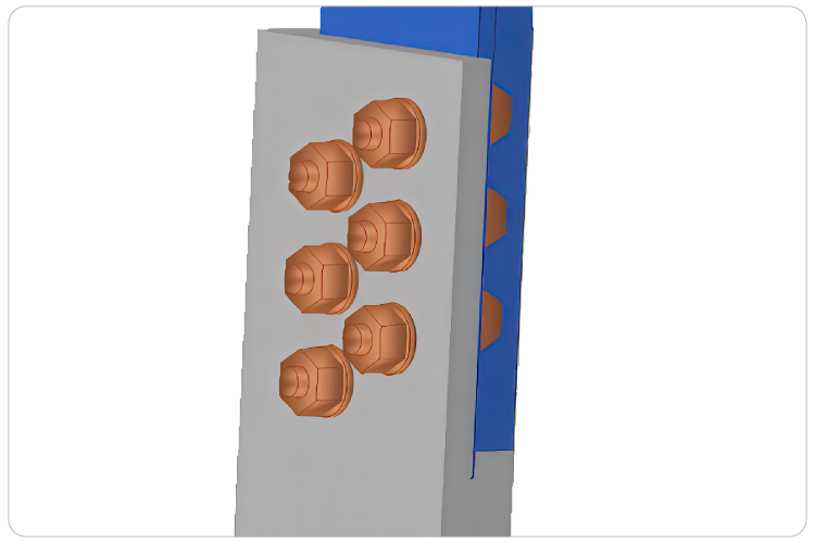
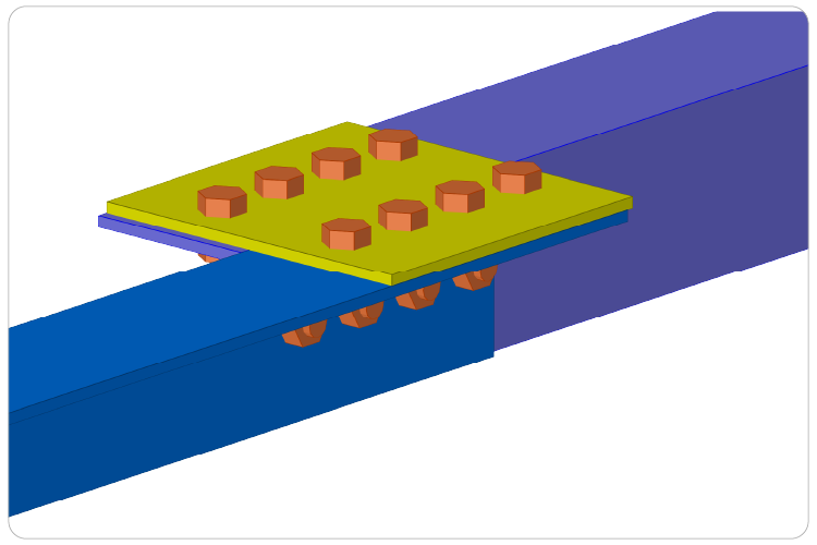
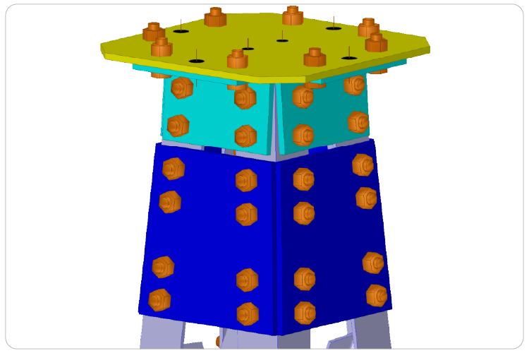
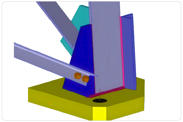
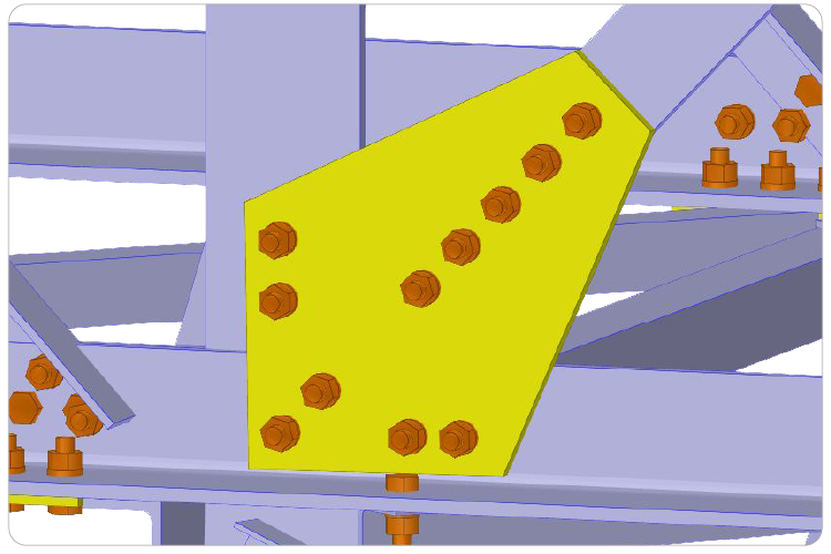
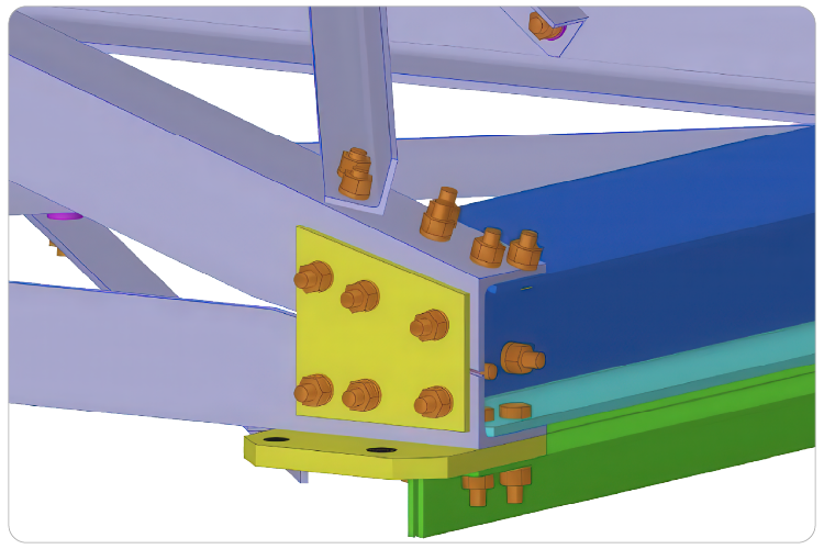
• Supports common types: bolts, splices, lap joints, base and cap plates
• Customizable parameters including bolt spacing, welds, and plate dimensions
• Adaptive updates with member size or alignment changes
• Define defaults for grades, bolts, welds, holes, plates, connections, and more
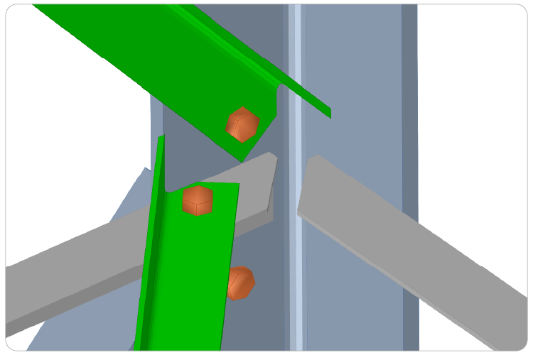
Machining Operations (End-Cut Tools)
• Member cuts: length cuts, copes, clips, blocks, flush, and plane cuts
• Advanced notches: dog bone, bevel, dovetail, needle, and rat/drain holes
• Custom slots and openings: rectangular or circular with rotation, roll, and depth control
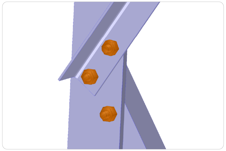
Smart Editing Tools
• Flexible connection setups: splices, bolts, overlaps, and back-to-back
• Edit connections by selection
• Washer and shim controls for precise thickness and placement
• Reusable bolt and hole groups with spacing, layout, and skew control
• Shop and field bolts plus head/nut inversion and through-bolt options
Block Libraries
• Save groups of custom objects, bolts, holes, and welds as reusable blocks
• Reusable libraries across projects and teams for consistency and efficiency
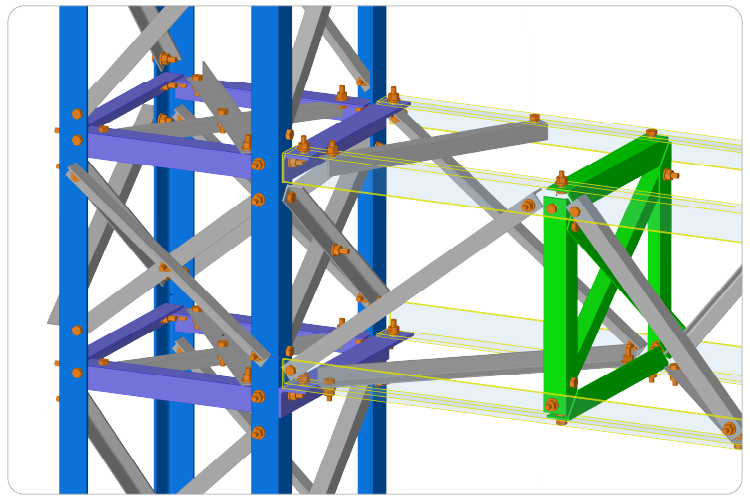
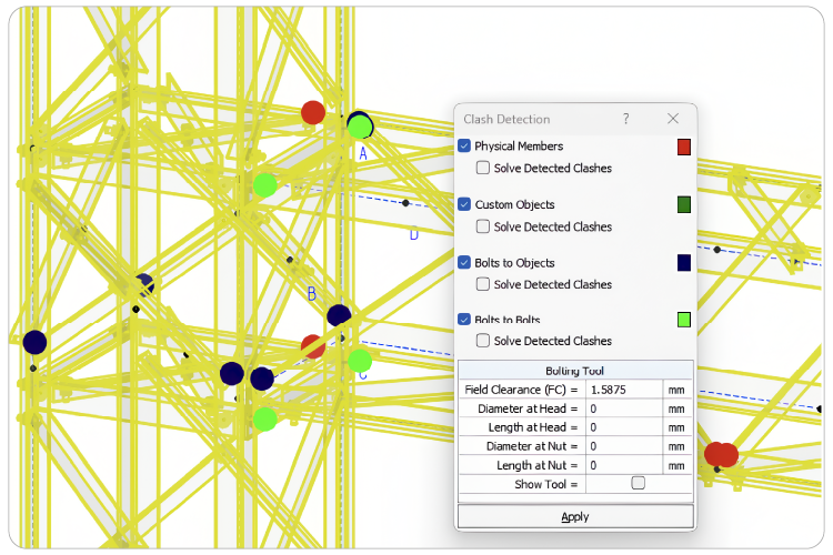
Clash Detection
• Identify and resolve interferences between members, connections, and custom objects
Drawings, BOM & Fabrication Integration
• Bill of Materials and quantitiesAutomatic Shop & General Assembly Drawings
• Quickly generate precise 2D drawings directly from your 3D tower model, including multiple face views, isometrics, and key plansCustom Sheet Setup & Drawing Configuration
• Define sheet sizes, scales, margins, and printer settings with automatic optimal layout selection or manual controlBill of Materials & Drawings
The Detailing phase focuses on generating all required drawings for fabrication, including 2D and 3D manufacturing drawings, engineering drawings, and detail drawings. VTS® extracts these directly from the fabrication model, ensuring consistency and precision across every component.
Editable DWG files and NC (Numerical Control) outputs are created automatically and can be exported directly, ready for CNC machine tools and shop-floor production.
including direct bolt connections, splices, base plates, cap plates, step bolts, and gussets
Fabrication (F) Mode
Take the next step to discover the VTS® Software by completing the following form. One of our experts will get in touch with you shortly. We look forward to assisting you with your inquiries and providing you with the information you need.
Virtual Tower Structures® (VTS) is a robust Microsoft Windows application tailored for the comprehensive analysis, design, connection design, fabrication and detailing of electrical substations and steel transmission structures.
The VTS® software is a technology built on a ribbon-based interface, offering a streamlined design element where tools, commands, and options are conveniently organized into tabs and groups for effortless access and navigation.
Virtual Tower Structures® (VTS) is a Level III technology, covering connection design, detailing and engineering drawings to produce the required information to manufacture the designed structures in a fully integrated manner and excluding as much as possible the use of protocols of data exchange.
Custom Reports & Report Presets
VTS® has the flexibility to generate customized reports tailored to users’ precise requirements. This feature allows the creation of concise custom reports containing only essential information, thereby minimizing report size. Additionally, users can establish predefined report templates and save report layout templates for convenient reuse in other files.
Create realistic Graphics
VTS® boasts a user-friendly interface, a robust analysis engine, comprehensive design checks, and advanced visualization tools, rendering the modeling of complex towers a seamless process. With a modern graphical user interface, users can effortlessly achieve realistic visualizations of their models. Additionally, powerful edition features allow to model very complex and non-standards towers.
Design new and existing towers
The design capabilities within VTS® offer an outstanding solution for both creating new towers and assessing existing structures when subjected to modified loads.
The VTS® software features comprehensive state-of-the-art structural analysis methods, including:
FEA Finite Elements Analysis, Static Analysis, Linear and Nonlinear Analysis, P-Delta Analysis, Natural Frequency Analysis, Static Equivalent Seismic Analysis, Dynamic Time-History Analysis, Seismic Time-History Analysis, Modal Analysis, Spatial Objects and Spatial Loads, Buckling Analysis, Response Spectrum Analysis, Advanced Section Stress Analysis, Torsion and Warping, Built Up Sections, Catenary Cables, Nonlinear springs, Diaphragm Analysis, Horizontal Notional Loads, Loads and Load Combinations.
State-of-the-art analysis tools
FEA including plates and shell elements
Torsion including restrained warping of open sections
Linear and exact non-linear cable elements (catenary cables)
Non-linear analysis using load control and displacement control strategy for better convergence
Possibility to add non-structural components using spatial objects
Design checks of sections according to the AISC 360 and CSA S16 standards.
Possibility to add non-structural components using spatial objects to automatically calculate dead, ice, and wind loads
Automatic handling of unidirectional elements such as tension-only members
VTS® software provides an exhaustive set of result features that include graphical views, diagrams, numerical tables, and text reports.
Benefit from Custom Reports capabilities to easily create tailored reports with editable content selection and arrangement. Take advantage of predefined templates and save your custom layouts for efficient use in future projects.
Advanced Reporting Feature:
· Select data types based on the application and modules used.
· Seamlessly add individual or multiple tables to the report from the selected group.
· Customize report settings that apply to the entire document, with the flexibility to override options for specific tables.
· Manage report layout with custom titles, table edits, and reorder tables using intuitive controls.
Generate the report for the whole model or a selection of elements.
Printing limit states results for the critical results only for each member or for physical member for the critical combination.
Virtual Tower Structures®
Want full access to our VTS training content? If you’ve purchased a license, simply fill out the form below with your registered email and product license key. Once verified, we’ll send you access to the full video tutorials.